

how to create a gui on a 4 wire resistive lcd screen
Arduino - LCD
In this Arduino LCD tutorial, we will learn how to connect an LCD (Liquid Crystal Display) to the Arduino board. LCDs are very popular and widely used in electronics projects for displaying information. There are many types of LCD. This tutorial takes LCD 16x2 (16 columns and 2 rows) as an example. The other LCDs are similar.
※ NOTE THAT:
If you want to simplify the wiring, You can use LCD I2C instead. See LCD I2C tutorial
| 1 | × | Arduino UNO or Genuino UNO | |
| 1 | × | USB 2.0 cable type A/B | |
| 1 | × | LCD | |
| 1 | × | Potentiometer | |
| 1 | × | Breadboard | |
| n | × | Jumper Wires |
Please note: These are affiliate links. If you buy the components through these links, We may get a commission at no extra cost to you. We appreciate it.
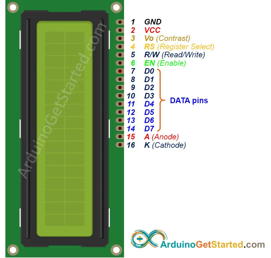
LCD has up to 16 pins. In the most common uses, we do NOT use all pins.
With the support of LiquidCrystal library, we even can use LCD WITHOUT knowing the meaning of these pins. However, if you are curious or want to know in-depth, let's see these pins and their functionality:
-
GND pin needs to be connected to GND (0V).
-
VCC pin the power supply for the LCD, needs to be connected to VCC (5V).
-
Vo (LCD Contrast) pin controls the contrast and brightness of the LCD, can be connected to 5V (the highest contrast and brightness), or connected to a potentiometer (to adjust to the contrast and brightness)
-
RS (Register Select) pin There are two kinds of data that need to send to LCD: command (to control LCD) and data. These two are sent on the same data bus. RS pin tells the LCD whether the data on the data bus is the commands or the data.
-
If we want to send the command to control LCD, we need to set RS pin to LOW (like set the cursor to a specific location, clear the display ...).
-
If we want to send the data to display on LCD, we need to set RS pin to HIGH.
-
R/W (Read/Write) pin is to select READ mode or WRITE mode.
-
If we want to read data from LCD, this pin needs to be set to HIGH.
-
If we want to send data to LCD, this pin needs to be set to LOW. Since we're just using this LCD as an OUTPUT device, we're going to tie this pin LOW.
-
EN (Enable) pin is used to enable the LCD. HIGH to enable the LCD, LOW to disable the LCD.
-
D0-D7 (Data Bus) pins carries data and command between Arduino and LCD. There are two modes to send data: 4-bit mode and 8-bit mode.
-
A-K (Anode & Cathode) pins are used to power the LCD backlight. A pin needs to be connected to VCC. K pin needs to be connected to GND.
-
8-bit mode: 8 bits of a byte are sent at the same time in pin D0 to D7.
-
4-bit mode: 8 bits of a byte is sent two times, each time 4 bits in pin D4 to D7.
8-bit mode is faster than the 4-bit mode, but use more pins than 4-bit mode. The mode selection is performed at the initialization process by sending a command to LCD.
This tutorial uses 4-bit mode, which is the most common-used.
In this mode, LCD's pins:
-
6 pins (RS, EN, D4, D5, D6, and D7) are connected to Arduino's pin.
-
4 pins (D0, D1, D2, and D3) are NOT connected.
-
6 remaining pins are connected to GND/VCC or potentiometer.
LCD pin table in 4-bit mode
| LCD PIN | CONNECTED TO | |
|---|---|---|
| 01 | GND | GND |
| 02 | VCC | 5V |
| 03 | Vo | 5V or potentiometer's pin |
| 04 | RS | An Arduino's pin |
| 05 | R/W | GND |
| 06 | EN | An Arduino's pin |
| 07 | D0 | NOT connected |
| 08 | D1 | NOT connected |
| 09 | D2 | NOT connected |
| 10 | D3 | NOT connected |
| 11 | D4 | An Arduino's pin |
| 12 | D5 | An Arduino's pin |
| 13 | D6 | An Arduino's pin |
| 14 | D7 | An Arduino's pin |
| 15 | A | 5V |
| 16 | K | GND |
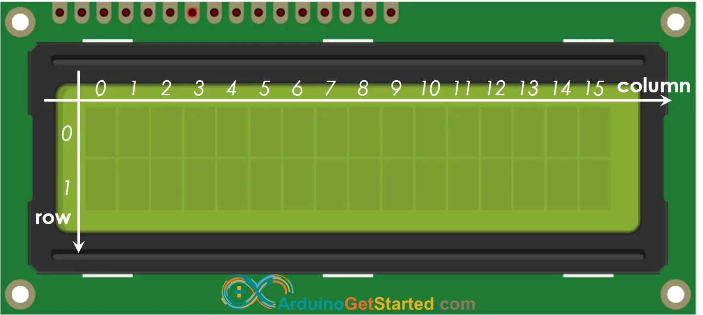
LCD 16x2 includes 16 columns and 2 rows. the conlums and rows are indexed from 0.
This section is the in-depth knowledge. DON'T worry if you don't understand. Ignore this section if it overloads you, and come back in another day. Keep reading the next sections.
The process of sending data (to be displayed) to LCD:
-
Arduino sets RS pin to HIGH (to select data register)
-
Arduino writes data to D4 → D7 pins (data bus).
-
LCD receives data on the data bus.
-
LCD stores the received data in the data resistor since the RS pin is HIGH. Then, LCD displays the data on the screen
The process of sending command (to control) to LCD (e.g, blink LCD, set the cursor to a specific location, clear the display ...):
-
Arduino sets RS pin to LOW (to select command register)
-
Arduino writes command to D4 → D7 pins (data bus).
-
LCD receives data on the data bus.
-
LCD stores the received data in the command resistor since the RS pin is LOW. Then, LCD takes action based on the value of the command.
Controlling LCD is a quite complicated task. Fortunately, thanks to the LiquidCrystal library, this library simplifies the process of controlling LCD for you so you don't need to know the low-level instructions. You just need to connect Arduino to LCD and use the functions of the library. The using LCD is a piece of cake.

Image is developed using Fritzing. Click to enlarge image
-
Include the library:
#include <LiquidCrystal.h>
-
Define which Arduino's pin connected to six LCD's pins: RS, EN, D4, D4, D6, D7
const int RS = 11, EN = 12, D4 = 2, D5 = 3, D6 = 4, D7 = 5;
One of the advantages of the library is that Arduino's pin connected to LCD is settable. This makes it flexible when you connect Arduino with LCD and other sensors/actuators.
-
Declare a LiquidCrystal object:
LiquidCrystal lcd(RS, EN, D4, D5, D6, D7);
-
Set up the LCD's number of columns and rows.
-
Move cursor to the desired position (column_index, row_index)
lcd.setCursor(column_index, row_index);
-
Print a message to the LCD.
lcd.print("Hello World!");
There are many things more that we can do with LCD (see Do More with LCD part)
※ NOTE THAT:
You can choose any six pins of Arduino to connect to LCD, as long as you specify the connected pin in the Arduino code.
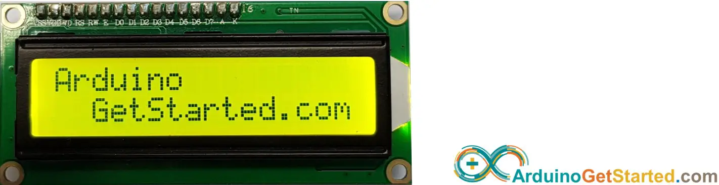
#include <LiquidCrystal.h> const int RS = 11, EN = 12, D4 = 2, D5 = 3, D6 = 4, D7 = 5; LiquidCrystal lcd(RS, EN, D4, D5, D6, D7); void setup() { lcd.begin(16, 2); lcd.setCursor(0, 0); lcd.print("Arduino"); lcd.setCursor(2, 1); lcd.print("GetStarted.com"); } void loop() { }
-
Copy the above code and open with Arduino IDE
-
Click Upload button on Arduino IDE to upload code to Arduino
-
See the result on LCD
-
Try modifying text and position
We are considering to make the video tutorials. If you think the video tutorials are essential, please subscribe to our YouTube channel to give us motivation for making the videos.
lcd.print() function supports only ASCII characters. If you want to display a special character or symbol (e.g. heart, angry bird), you need to use the below character generator.
LCD 16x2 can display 32 characters (2 rows and 16 columns). Each character is composed of 40 pixels (8 rows and 5 columns).
![]()
The character generator represents a character (40 pixels). You just need to do the following steps:
Click on each pixel to select/deselect
Copy below custom character code
Replace the customChar[8] in the below code
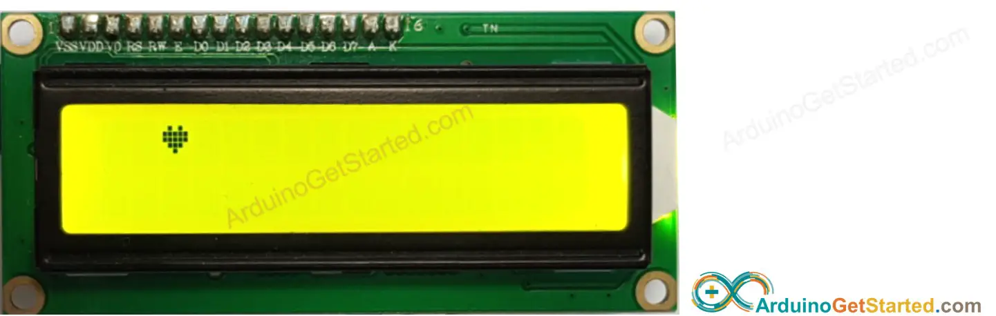
#include <LiquidCrystal.h> const int RS = 11, EN = 12, D4 = 2, D5 = 3, D6 = 4, D7 = 5; LiquidCrystal lcd(RS, EN, D4, D5, D6, D7); byte customChar[8] = { 0b00000, 0b01010, 0b11111, 0b11111, 0b01110, 0b00100, 0b00000, 0b00000 }; void setup() { lcd.begin(16, 2); lcd.createChar(0, customChar); lcd.setCursor(2, 0); lcd.write((byte)0); } void loop() { }
Result on LCD:
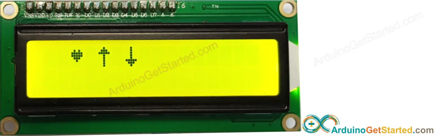
We can create up to 8 custom characters (indexed 0 to 7). The below example creates and displays three characters.
#include <LiquidCrystal.h> const int RS = 11, EN = 12, D4 = 2, D5 = 3, D6 = 4, D7 = 5; LiquidCrystal lcd(RS, EN, D4, D5, D6, D7); byte customChar0[8] = { 0b00000, 0b01010, 0b11111, 0b11111, 0b01110, 0b00100, 0b00000, 0b00000 }; byte customChar1[8] = { 0b00100, 0b01110, 0b11111, 0b00100, 0b00100, 0b00100, 0b00100, 0b00100 }; byte customChar2[8] = { 0b00100, 0b00100, 0b00100, 0b00100, 0b00100, 0b11111, 0b01110, 0b00100 }; void setup() { lcd.begin(16, 2); lcd.createChar(0, customChar0); lcd.createChar(1, customChar1); lcd.createChar(2, customChar2); lcd.setCursor(2, 0); lcd.write((byte)0); lcd.setCursor(4, 0); lcd.write((byte)1); lcd.setCursor(6, 0); lcd.write((byte)2); } void loop() { }
Result on LCD:
-
Use the above character generator to create binary code for the custom character.
-
Declare the binary code for the custom character (copy from above step)
byte customChar[8] = { 0b00000, 0b01010, 0b11111, 0b11111, 0b01110, 0b00100, 0b00000, 0b00000 };
-
Create custom character and assign to an index value (from 0 to 7) in setup() function
lcd.createChar(index, customChar);
-
Print the custom character in LCD anytime, anywhere (in setup() or loop() function)
lcd.setCursor(column, row); lcd.write((byte)index);
Use LCD to do one of the following projects:
-
Displaying the pressed key of the keypad on LCD. Hint: Refer to Arduino - Keypad
The above code also works with the following LCDs:
※ OUR MESSAGES
-
You can share the link of this tutorial anywhere. Howerver, please do not copy the content to share on other websites. We took a lot of time and effort to create the content of this tutorial, please respect our work!
Follow Us
how to create a gui on a 4 wire resistive lcd screen
Source: https://arduinogetstarted.com/tutorials/arduino-lcd
Posted by: gordonlievaight.blogspot.com
0 Response to "how to create a gui on a 4 wire resistive lcd screen"
Post a Comment